SPRESENSE Wi-Fi ADD-ON BOARD / iS110B

Wi-Fi connectivity
for SPRESENSE.

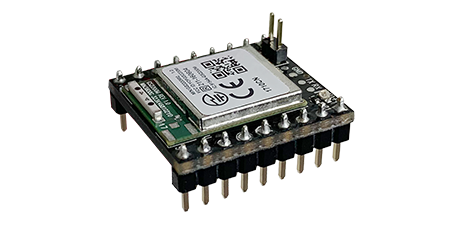
A Wi-Fi add-on board for Sony SPRESENSE, built around the Telit GS2200MIZ with 2.4GHz Wi-Fi and an SPI interface.

IDY iS110B
iS110BSPRESENSE Wi-Fi ADD-ON BOARD
2.4GHzWi-Fi
802.11b/g/nSTANDARD
SPISTANDARD INTERFACE
GS2200MIZMODULE
01OVERVIEW

Add wireless connectivity
with a compact board.

Supports access point and station modes, Wi-Fi Direct and WPS. A chip antenna is built in; SPI is standard and UART is optional. The SPRESENSE main board is sold separately.
01 / CONNECT

Wi-Fi for SPRESENSE

A compact add-on board designed for SPRESENSE.

02 / INTERFACE

Standard SPI interface

SPI is standard; UART is available as an option.

03 / SERVICE

Network services

Supports protocols including DHCP, HTTPS and MQTT.

02APPLICATIONS

Built for long-term
field operation.

01

Remote equipment monitoring

Collect equipment and sensor data over Wi-Fi.

02

Digital signage

Connect SPRESENSE-based display equipment to a network.

03

Facility monitoring

Collect information from solar installations and controlled agriculture.

03SPECIFICATIONS

Key specifications

Wi-Fi2.4GHz
STANDARD802.11b/g/n
STANDARD INTERFACESPI
MODULEGS2200MIZ
TECHNICAL SPECIFICATIONSiS110B SERIES
01WIRELESS
ModuleTelit GS2200MIZ
Wi-FiIEEE 802.11b/g/n (2.4GHz)
ModesAccess point / station, Wi-Fi Direct, WPS
Transmit power (Typical)802.11b 1Mbps: +15dBm / 802.11g 6Mbps: +14dBm / 802.11n MCS0: +14dBm
Receive sensitivity (Typical)802.11b 1Mbps: -91dBm / 802.11g 6Mbps: -88dBm / 802.11n MCS0: -88dBm
AntennaBuilt-in chip antenna
02INTERFACE
Host interfaceSPI (standard), UART (optional)
ServicesDHCP, HTTPS, SNTP, CoAP, DTLS, MQTT
03ENVIRONMENT
Operating Temperature-40–+70°C
CertificationTELEC / FCC / CE
NoteSPRESENSE main board sold separately. Throughput depends on the SPRESENSE SPI clock.

Development resources and support

IDY does not provide direct software support.

Documentation and sample code

Check your board revision and development environment before using the published documentation or sample code. The current GitHub source includes Type-C handling. Historical changes and patches are reference material for legacy samples, not instructions to patch the current source.

Development questions

For sample-code issues, check existing GitHub Issues and include your board revision, development environment and reproduction steps when reporting a problem. For SPRESENSE development tools and programming questions, follow Sony’s official guidance to the developer forum.

Product inquiries to IDY

Contact IDY about hardware faults or custom development and customization projects. IDY does not sell iS110B directly. For purchases, use the stores listed on the product page.

04INSTALLATION & PINOUT

Installation and pin connections

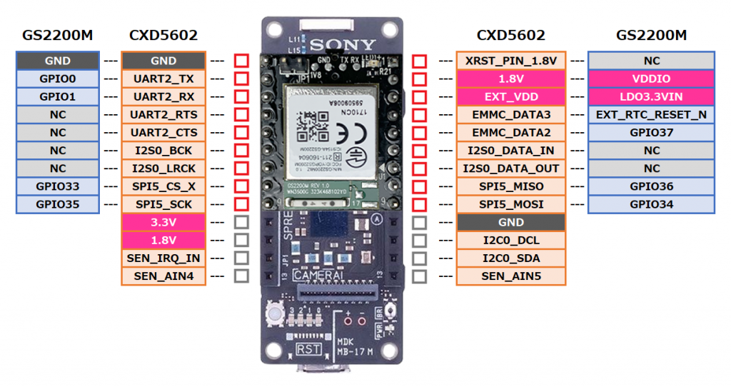
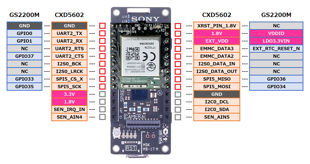
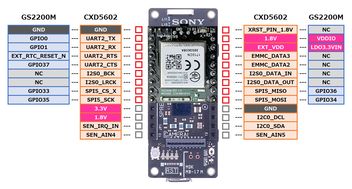
Mount the board using the upper nine pins on each side of SPRESENSE, leaving four pins unused at the bottom of each side. Connections differ by board revision; use the diagram for your board.

On smaller screens, scroll each diagram horizontally. Select a diagram to open it at full resolution in a new tab.

V1.0C pin connections
Pin connections between iS110B V1.0C and SPRESENSE CXD5602, including power, ground, SPI and control signals.
V1.0B pin connections
Pin connections between iS110B V1.0B and SPRESENSE CXD5602, including power, ground, SPI and control signals.
V1.0A pin connections
Pin connections between iS110B V1.0A and SPRESENSE CXD5602, including power, ground, SPI and control signals.
05BOARD REVISIONS

Board revision identification

Board revisionIdentificationChanges and purpose
V1.0AREV:1.0 marking without a red dotInitial revision
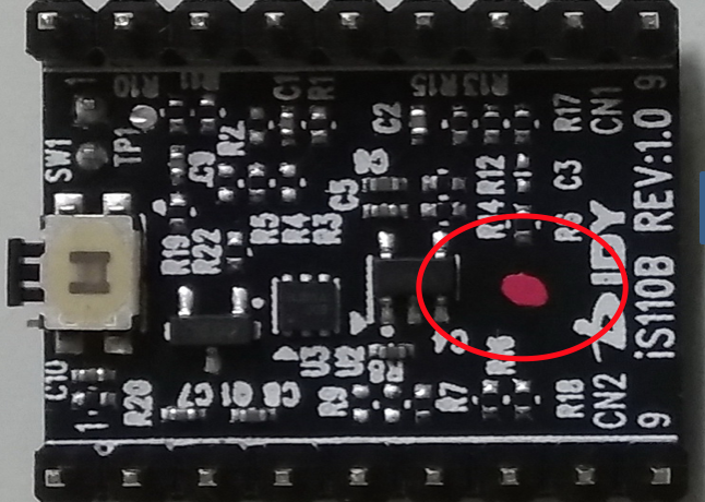
V1.0BREV:1.0 marking with a red dotRemove R2 and add R4 to allow firmware programming over UART while the SPRESENSE UART pins are configured for UART operation.
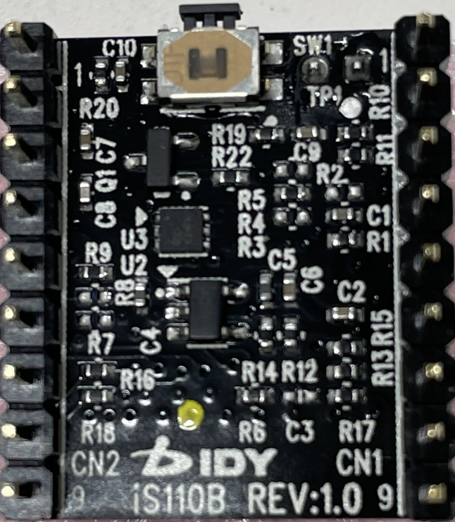
V1.0CREV:1.0 marking with a yellow dotRemove R7 and add R9 to make the SPRESENSE UART pins available for separate use while GS2200MIZ is connected over SPI.
V1.0B: red dot
Red dot identifying the iS110B V1.0B board
V1.0C: yellow dot
Yellow dot identifying the iS110B V1.0C board

Firmware versions at shipment

The original shipment guidance lists firmware 5.7.1 for V1.0A and 5.8.1 for V1.0B and later. V1.0A boards with red-black-red marks on GS2200MIZ also have 5.8.1 installed. Use version 5.8.1 or later for an MQTT connection to Azure IoT Hub.

06PIN CUSTOMIZATION

Changing pin connections

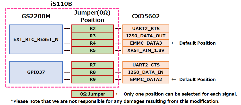
The connections for EXT_RTC_RESET_N and GPIO37 can be changed by repositioning the 0Ω jumpers. Select only one position for each signal. The V1.0C defaults are R4 (EMMC_DATA3) for EXT_RTC_RESET_N and R9 (EMMC_DATA2) for GPIO37.

V1.0C jumper configuration
Jumper options: R2, R3, R4 or R5 for EXT_RTC_RESET_N, and R7, R8 or R9 for GPIO37. Choose one position per signal; defaults are R4 and R9.

Damage resulting from this modification is not covered by warranty.

08WHERE TO BUY

Where to buy

Please purchase iS110B from CoreStaff Online or the Restar Online Store. IDY does not sell this product directly.

Please check the stores for pricing, availability, delivery times and order inquiries. The linked store pages are in Japanese.