Measure beyond the radio.Engineer the complete product.Measure beyondthe radio.Engineer thecomplete product.
We measure each path from radio reference throughput through product internals, USB or PCIe, operating systems and applications, then engineer thermal, mechanical and recovery performance into the finished product.
08 / DEVICE & PATH THROUGHPUT
From radio reference throughputto device and path performance.From radio referencethroughput to deviceand path performance.
Using the same MT8000A radio conditions, IDY measures iR800B 10GbE routing, iperf3 running inside iR800B, and iS201B connected directly to a PC. Radio reference throughput is distinguished from throughput measured through each product and path.
3PATHSMEASURED BY PATH
DOWNLINK DLRADIO PROFILE 01 / 3,146.694 Mbps
Public-network-aligned DL profile
iR800B / 10GbE E2E ROUTINGUSB 1.94 GbpsPCIe 2.34 Gbpsiperf3 on LAN-side PC
iS201B / DIRECT USBUbuntu 3.03 GbpsWindows 3.06 GbpsiS201B connected directly to PC
UPLINK ULRADIO PROFILE 02 / 647.489 Mbps
Semi-synchronous TDD3 / UL profile
iR800B / 10GbE E2E ROUTINGUSB 617〜618 MbpsPCIe 622 Mbpsiperf3 on LAN-side PC
UPLINK ULRADIO PROFILE 03 / 1,138.34 Mbps
Asynchronous / UL-maximized
iR800B / 10GbE E2E ROUTINGUSB 819 MbpsPCIe 785 Mbpsiperf3 on LAN-side PC
iS201B / DIRECT USB1,020 MbpsiS201B connected directly to PC
USB / PCIe PROCESSING ANALYSIS
The same radio profile performs differently across interfaces.
The iR800B routing results under the public-network-aligned DL profile are analyzed by thread count, zero-copy and packet steering. USB remains stable with fewer threads, while PCIe reaches peak performance through multi-threaded parallel processing.
USB1.94 GbpsPeak at 4 threads
1T1920
2T1920
4T1940
8T1740
16T1590
Host controlled. Zero-copy with fewer threads produced stable throughput, while driver-level device recovery remains practical.
PCIe2.34 GbpsPeak at 16 threads
1T985
2T1550
4T2210
8T2200
16T2340
DMA based. Multiple threads and rps_cpus achieved a peak approximately 20% above USB, but recovery requires operating-system and kernel-level reinitialization.
Results are measurements from the stated test configurations. iperf3 runs on the LAN-side PC for iR800B routing, inside iR800B for the standalone gateway test, and on the directly connected PC for iS201B. Because measurement points and paths differ, these figures are not a simple like-for-like product comparison. The standard iR800B configuration uses USB because device recovery matters alongside peak throughput.
CONTINUOUS HIGH-LOAD TEST / iR800B
Approximately 70 minutes under continuous high load
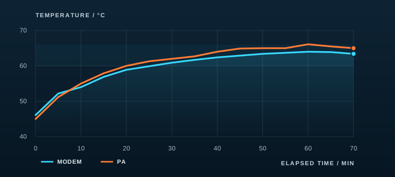
With ambient temperature around 30°C, an iR800B ran iperf3 traffic for approximately 70 minutes. Effective downlink throughput was around 1.7 Gbps. Internal modem and PA temperatures rose, then broadly settled in the 60°C range.
~70MINCONTINUOUS TRAFFIC
Internal iR800B modem and PA temperature trends (approximately 70 minutes, ambient around 30°C)
This chart reconstructs approximate modem and PA temperatures from the approximately 70-minute internal test record. It does not show CPU temperature or a throughput time series. The approximately 1.7 Gbps effective downlink rate applies to this test configuration and is not a guaranteed rating.
ADDITIONAL THERMAL VALIDATION / iR800B
One-hour traffic test without an external Peltier cooler.
In a separate internal test, iperf3 downlink traffic ran for one hour across four USB and PCIe configurations, covering routing and standalone-board paths. Without an external Peltier cooler on the product enclosure, end-of-test modem temperature was approximately 61–65°C, PA temperature 62–65°C, and CPU temperature 71–78°C.
Conditions: iperf3 -R -Z -P 16 -t 3600; the enclosure was cooled to approximately 40°C before testing. Ranges show end-of-test temperatures across four configurations. A throughput drop with suspected thermal effects in the test setup was also recorded. These observations do not guarantee sustained throughput across all paths or stability beyond the test duration. This test is separate from the approximately 70-minute study above.
09 / DEVICE INTEGRATION
Bring 5G directlyto Windows and Linux devices.Bring 5G directlyto Windows andLinux devices.
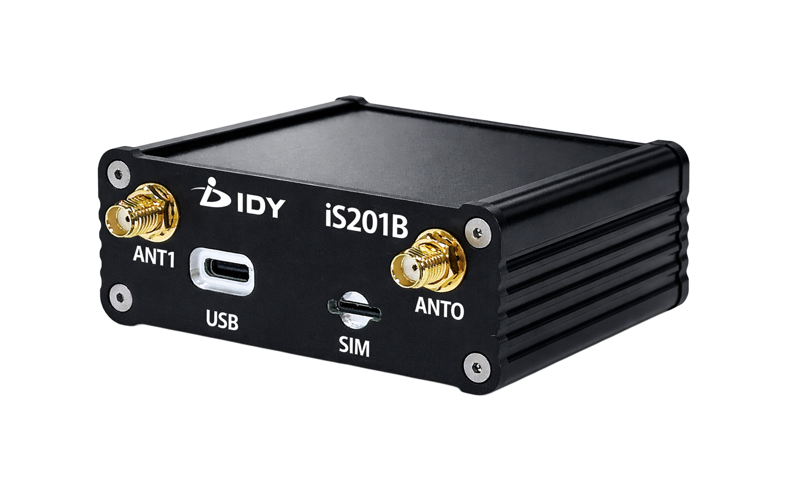
iS201B connects directly over USB not only to PCs, but also to drones, AGVs and AMRs, machine tools and control equipment running Windows or Linux. IDY implements 5G as a complete system spanning the operating system, drivers, antennas, communications settings and application processing.
USBDIRECTCOMMON 5G INTERFACE
HOST PLATFORM
WindowsLinux
USB connectivity through Qualcomm drivers
USB
PCPC
5G USBiS201B
Measurement, video and edge processing
UAVDRONE
5G USBiS201B
Video transmission and remote control
AGVAGV / AMR
5G USBiS201B
Mobile and autonomous transport
CNCMACHINE / CONTROL
5G USBiS201B
Equipment connectivity and remote monitoring
WINDOWS / DIRECT CONNECTION3.06 GbpsiS201B standalone DL evaluation
UBUNTU / DIRECT CONNECTION3.03 GbpsiS201B standalone DL evaluation
The same iS201B USB architecture extends across Windows and Linux equipment for different applications, supported by a common product, driver and validation foundation.
Measurement conditions: 5G SA n79, 2CC CA 200MHz, 4×4 MIMO, with iS201B connected directly to a PC over USB. Target equipment requires a compatible operating system, USB interface, driver and power configuration.
12 / THERMAL ENGINEERING
Move heat into the enclosure.Without relying on a fan.Move heat intothe enclosure.Without relying on a fan.
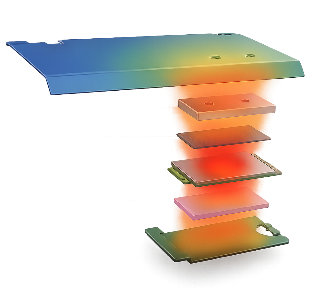
The iR730B uses a six-layer sandwich thermal structure engineered across the complete product to transfer 5G heat into the enclosure. IDY compared configurations with and without the heatsink and validated operation at high ambient temperature to achieve stable fanless operation without moving parts.
45°CREDUCTION IN PEAK 5G SUBSYSTEM TEMPERATURE
6-LAYER SANDWICH THERMAL DESIGNA six-layer path transfers 5G heat into the enclosure.
WITHOUT HEATSINK89°CNo heatsink
→
TOP ALUMINUM HEATSINK44°CTop aluminum heatsink
HIGH TEMPERATURE VERIFICATION80°C maximum 5G subsystem temperature at 60°C ambient.
No migration occurred with the top aluminum heatsink configuration, suppressing thermal throttling even at high ambient temperature.
FANLESSNO MOVING PARTSENCLOSURE HEAT PATH
Comparison conditions: iR730B-001, 25°C ambient, comparing maximum 5G subsystem temperature without a heatsink and with a top aluminum heatsink. High-temperature validation was performed at 60°C ambient.
13 / MECHANICAL RELIABILITY
Not only shaken.Tested while connected.Not only shaken.Tested while connected.
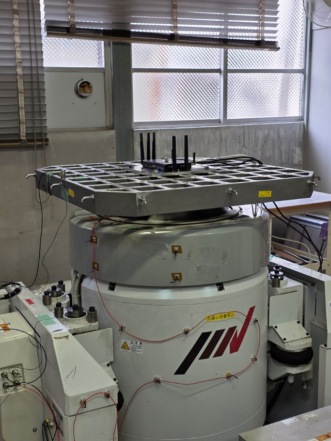
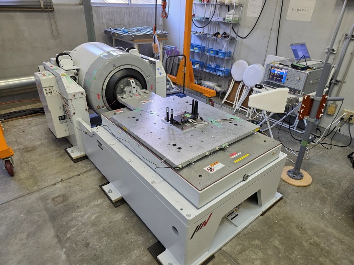
The iR800B is tested for railway and automotive vibration environments through functional, endurance and shock testing on the X, Y and Z axes. Communications and interfaces are monitored during testing, followed by functional, external and internal inspection.
3AXESX / Y / Z FUNCTION & ENDURANCE
ACTUAL TEST PHOTO
RAILWAY / JIS E 4031:2013 CLASS 1A
Five-hour endurance per axis and shock testing up to 30G.
Functional vibration, five-hour endurance testing on each axis and shock testing all passed, including 30G / 18 ms transport and handling shock.
5 HOURS × 3 AXES30G / 18msPASS
ACTUAL TEST PHOTO
AUTOMOTIVE / JIS D 1601:1995
Three-axis 3.0G validation for automotive environments.
Evaluated to classifications 1A / 1B / 2A / 2B at acceleration level 30. The unit passed 3.0G functional and endurance testing on every axis and all post-test inspections.
Refer to product specifications for applicable models, standards and detailed test conditions. Vibration and shock testing does not guarantee uninterrupted operation under every installation and operating condition.
14 / FULL-STACK WIRELESS ENGINEERING
From the radio networkto the edge device.From the radionetwork to theedge device.
IDY combines industrial communication product development with engineering knowledge spanning base-station and RAN technologies, including PHY and protocol stacks. We engineer products, RF, antennas, embedded software, network access and recovery control as one resilient field system.
01
RAN / BASE STATION
Radio access network
Understand radio-access behavior beyond the device side.
4G LTE / 5G NR
PHY / PROTOCOL STACK
RAN INTERWORKING
02
RADIO / RF
Radio, RF and antenna
Optimize the radio system across spectrum, propagation and installation.
5G / LTE / MULTI-RAT
MIMO / RF / ANTENNA
BAND / CARRIER VALIDATION
03
PRODUCT / EDGE DEVICE
Communication products
Develop industrial gateways and communication devices across hardware and embedded software.
5G / LTE GATEWAY
10GbE / SFP+ / USB-C
SIM / STATE / POWER CONTROL
04
EDGE / OPERATION
Edge and operations
Embed link decisions, switching, recovery and monitoring into operations.
MULTI-SIM / FAILOVER
MONITORING / RECOVERY
EDGE / REMOTE MANAGEMENT
END-TO-END ENGINEERING
SYSTEM DESIGNVALIDATIONCERTIFICATIONFIELD OPTIMIZATION
Resilient connectivity begins with products and networks engineered as one.
Understanding radio access, devices, antennas and operations together is what turns connectivity into a system that keeps working in the field.
Resilient connectivity,built through engineering evidence.Resilient connectivity,built throughengineering evidence.
IDY validates the complete system, from radio access and wireless links through in-product communications, embedded SoCs, operating systems, applications and real operating environments. We apply that accumulated engineering knowledge to products and solutions that help society keep communicating.
Qualcomm is a trademark or registered trademark of Qualcomm Incorporated. Microsoft and Windows are trademarks of the Microsoft group of companies. Linux is the registered trademark of Linus Torvalds in Japan and other countries. All other company and product names are trademarks or registered trademarks of their respective owners.