Connectivity that survivesnetwork and generation changes.Connectivity thatsurvives network andgeneration changes.
We engineer LTE, 5G, multiple carriers, Multi-SIM and regional BWA as one resilient connectivity system with autonomous recovery.
NETWORK EVOLUTION
From LTE to 5G. Infrastructure is entering a network transition.
Since the launch of 5G services, easy-to-deploy DSS has expanded while refarming of LTE spectrum to 5G NR has progressed in parallel. Industrial systems therefore need connectivity designed to operate throughout this transition.
LTE5G NR
DSSLTE / 5G share spectrum
REFARMINGLTE spectrum reallocated to 5G NR
20205G service launch
NOWDSS and refarming progress in parallel
2030Toward a 5G-centric network
2020LTE + 5G START5G service launch
NETWORK MIGRATIONDSS + REFARMINGDSS and spectrum refarming progress in parallel
2030 / 5G MULTI-RATLTE + 5GBridge the transition toward a 5G-centric era
LTE-ONLYLTE-only deviceMore exposed to congestion as usable LTE spectrum narrows
5G MULTI-RATUse both LTE + 5GUse both network generations through the transition
LTE-ONLY / FUTURE RISKConnected today, but exposed to future spectrum reduction and congestion.
As LTE spectrum narrows, congestion can have a greater impact on communications.
Non-stop connectivity is not a single product. It is an architecture built by layering resilient technologies.
06 / LOCAL 5G LATENCY RESEARCH
Isolating latency fromthe radio network to the edge.Isolating latencyfrom the radio networkto the edge.
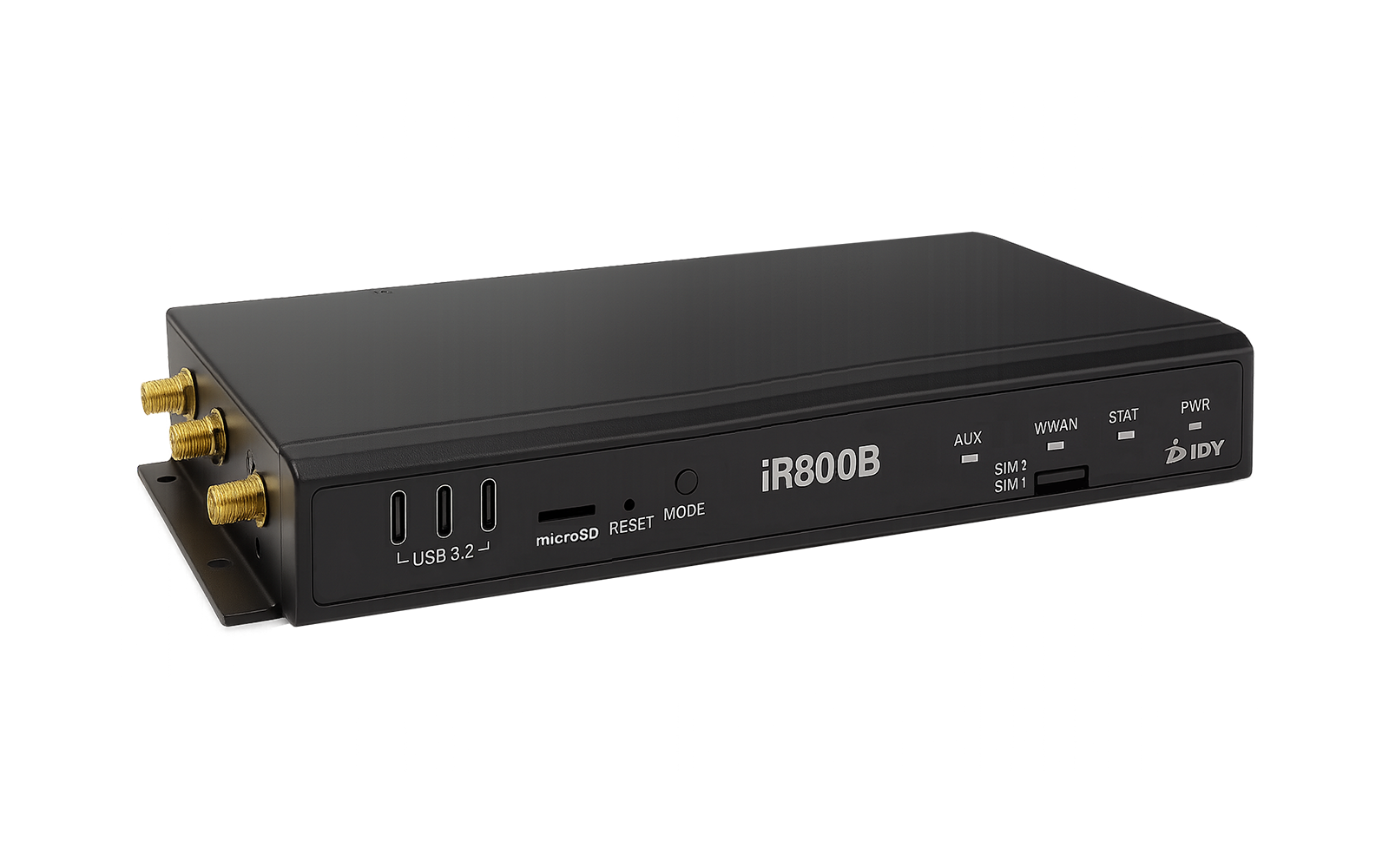
In a local 5G evaluation conducted with a technology partner, IDY examined latency across the 5G radio segment, iR800B-102 forwarding and the complete end-to-end path over an L2 overlay. The architecture, test conditions and results are summarized below.
9.3–9.6msEnd-to-end average RTT
CORE SIDETEST HOSTL2 OVERLAY
WIRED DATA NETWORK
LOCAL 5G5GC + gNB / RUn79 / 100MHz
5G NR7.5–7.7ms
EDGE GATEWAYiR800B-102UE + FORWARDING
VXLAN / L2+ ≈2ms
EDGE SIDETEST HOSTEND-TO-END
7.5–7.7msAverage RTT across the 5G segment
≈2msDevice forwarding and overlay overhead
0%Packet loss at the 100Mbps offered downlink load
LATENCY UNDER LOAD
Latency under traffic and at the capacity boundary.
A 100-byte RTT probe ran alongside UDP traffic in separate downlink and uplink tests. Average latency, the 99th percentile (P99) and packet loss show how the path behaved under load.
Direction / state
Offered → delivered
Mean RTT
P99 RTT
Loss
DLUnder downlink load
70 → 69.9 Mbps
13.72 ms
16.36 ms
0%
ULUnder uplink load
20 → 20.0 Mbps
10.66 ms
13.98 ms
0%
ULAt configured limit
30 → 27.4 Mbps
225.7 ms
253.2 ms
8.3%
In this test, the uplink path was limited to about 30Mbps by the base-station configuration. Near that limit, queueing increased RTT and packet loss. This describes this configuration, not the uplink capability limit of iR800B-102.
Method: each offered load ran for approximately 60 seconds, with one run per direction. RTT was measured with sockperf at 100 bytes and 100 packets/s alongside iperf3 UDP traffic; delivered rates are received throughput. These are single-condition observations, not guaranteed speed or latency.
Conditions: local 5G n79 with 100MHz bandwidth over an L2 overlay. Only the 5G path was active; seamless failover and dual-path performance were outside this test scope.
10 / MULTI-SIM & RECOVERY CONTROL
Multiple links alonedo not create resilience.Multiple links alonedo not createresilience.
Resilience is determined not by SIM count alone, but by how many networks remain registered, how many links can carry traffic concurrently and which path can take over after a failure. IDY engineers link monitoring, path selection, post-switch validation and recovery decisions as one communications-control system.
3SIM3 REGISTRATION / 2 ACTIVE
ACTIVEREGISTERED / STANDBYNOT REGISTERED
3GPP REL.16 CLASS
iR800B-102 + iS201B
3 SIM / 2 REG / 2 ACTIVE
iR800B-102
USB 3.2
iS201B
SIM A / INTERNALREGISTEREDACTIVE
SIM B / INTERNALNOT REGISTERED—
SIM C / USB PATHREGISTEREDACTIVE
Two paths can operate as Active links. Switching to internal SIM B requires network registration, so recovery takes longer than with a registered standby path.
3GPP REL.17 CLASS
iR800B-107 + iS201B
3 SIM / 3 REG / 2 ACTIVE
iR800B-107
USB 3.2
iS201B
SIM A / INTERNALREGISTEREDACTIVE
SIM B / INTERNALREGISTEREDSTANDBY
SIM C / USB PATHREGISTEREDACTIVE
All three networks remain registered, with two Active links and one Standby path. Keeping the standby network registered reduces the processing required before switching compared with a re-registration architecture.
FAILURE DETECTION TO SERVICE RECOVERY
Do not stop at switching. Confirm that communications have recovered.
01MONITORContinuously monitor reachability, quality and link state
02DETECTDistinguish transient loss from sustained failure
03SELECTSelect a path using registration and Active state
04SWITCHUpdate routing and the communications path
05VERIFYVerify end-to-end service on the new path
06RECOVERMonitor the recovered link and manage return conditions
REGISTRATIONA registered standby path is prepared to switch.
ACTIVE LINKSTwo Active links are two independent WAN paths.
CONTROL POLICYSwitch and return policies are engineered for the operation.
“Two Active” indicates that two WAN links are concurrently available. It does not by itself mean automatic bandwidth aggregation or seamless switching for every application. Actual recovery time and continuity depend on registration state, carrier, detection policy, routing and application-level retransmission and session design.
11 / REGIONAL BWA INTEROPERABILITY
Regional BWA, validatedfor CATV connectivity.Regional BWA,validated for CATVconnectivity.
With the cooperation of Tama Cable Television Network, IDY evaluated connectivity and data communication using its Regional BWA SIM across IDY LTE routers, 5G/LTE gateways and 5G USB modems. The results confirm interoperability for nationwide deployment based on the Regional BWA roaming framework among CATV operators.
Scope: network attachment and data communication on Regional BWA Band 41. Deployment requires configuration appropriate to each operator’s SIM contract, APN, authentication and roaming conditions.
15 / ENGINEERING EVIDENCE
Engineering demonstratedthrough design and measurement.Engineeringdemonstratedthrough designand measurement.
These examples present engineering scope and measured findings from development and validation work. Customer names and project-specific identifiers are intentionally omitted.
01
60GHz / MULTI-RAT / TELEOPERATION
Low-latency edge design combining 60GHz wireless and 5G
IDY integrated 60GHz wireless into an iR800B-based teleoperation system. The architecture carries immersive video and audio, control traffic and time synchronization while prioritizing low latency and low jitter.
Multi-RAT architecture across 60GHz, 5G and Wi-Fi
Separate evaluation of media and control traffic
Integration into a production edge gateway
02
LOCAL 5G / n79 / LATENCY ANALYSIS
Latency measured from the radio network through the overlay
In an n79 100MHz local 5G environment, IDY measured a path including iR800B and an L2 overlay. Average RTT was 7.5–7.7ms across the 5G segment and 9.3–9.6ms end to end, isolating approximately 2ms of device and overlay overhead.
Zero downlink packet loss through the 100Mbps test load
Separated base-station modulation limits from device performance
Quantified bufferbloat beyond the configured capacity
03
MOBILITY / PRIVATE 5G / UE CONTROL
Device-side control for mobile private 5G systems
For a high-speed mobility test environment, IDY examined device functions that identify authorized areas and multiple cells before allowing transmission. The design translates regulatory conditions, cell selection and operational visibility into product behavior.
Access control using PLMN, band, ARFCN and multiple PCI values
Advanced routing with multiple LANs, GRE, ACL and MTU control
Operational visibility for PCI, RSRP, SINR and related radio data
Evaluation of closed-access control including 3GPP Rel.16 CAG
* Results were measured under specific system, configuration and radio conditions and do not guarantee identical performance in every deployment.


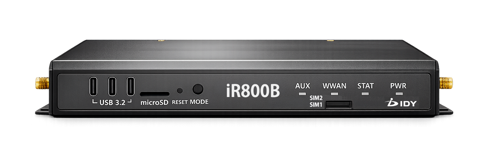 iR800B-102
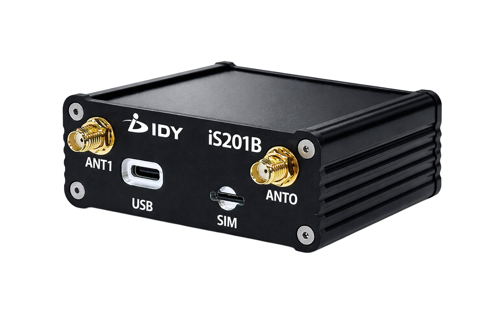 iS201B